Equipment of digital transmission systems of television and sound broadcasting
TECHNICAL DESCRIPTION for digital transmission systems of television and audio broadcasting, the use of which is possible as part of the radio relay system (RRS) "Era M", and in various configurations of Studio equipment of TV and radio companies.
1. Name and completeness of communications means
Digital transmission systems for television and sound broadcasting include the following equipment:
Multiplexers-modulators:
- DTVS2-8ASI-Basic, DTVS2-5ASI-Basic, DTVS2-4ASI-Basic;
- DVBC-4ASI-Basic, DVBC-5ASI-Basic, DVBC-8ASI-Basic;
Multiplexer:
- DTVC-5ASI-REMUX-Basic;
Receivers-decoders (RD) :
- RD DVB-T, RD DVB-S/S2;
IP decoder with composite and HDMI outputs:
- HD IP Receiver;
Encoders (video encoders) with MPEG-4 and /or MPEG-2 compression:
- COD-HDSDI-MP4/2; COD-2хHDSDI-MP4/2;
- COD-4хHDSDI- MP4/2; COD-HDHDMI-MP4/2
- COD-2xHDMI-MP4/2; COD-4хHDHDMI-MP4/2;
- COD-2хSDI/CVBS-MP2;
Encoder-transcoder:
- TRANSCOD-MPEG4-2;
Time shifted TV channel multiplexer:
- ASI Time Shifting;
On-camera wireless systems:
- VideoLink-800, VideoLink-2300.
2. Purpose of the communications means and their functions
2.1. Multiplexers-modulators
2.1.1. Multiplexers-modulators for satellite systems are designed to combine up to 8 ASI input digital streams into an IP stream and its modulation by QPSK and 8 PSK methods for video signals transmission over RRL (if output signal tuning on frequency in the range from 70 -1,700 MHz) and broadcasting to the satellite (DVB-S/S2 standards). Multiplexers-modulators provide operation with both SD (Standard Definition) and HD (High Definition) channels.
2.1.2. Multiplexers-modulators for cable systems are intended to combine up to 8 ASI input digital streams into an IP stream and its modulationt by QAM 32/64/128/256 methods to distribute it across cable systems. Up to 4 DVB-C packages are available in the group spectrum. They opertate with both SD (Standard Definition) and HD (High Definition) channels.
2.2. Multiplexer
Multiplexer provides the formation of required software package from 5 input ASI streams and its transmission to the ASI output or IP output
2.3. Receivers-decoders
Receivers-decoders provide reception, demodulation of the received signals and FEC-decoding of digital streams of signals according to DVB-T or DVB-S standards, decoding of digital transport streams and formation of picture signals, soundtrack, user data, service information according to MPEG standards.
Receivers-decoders have the following interfaces:
- RD DVB-T, RD DVB-S/S2: analog (composite PAL/SECAM) and digital (SDI) video; ASI transport layer interface;
- HD Receiver IP: analog (composite PAL/SECAM) and digital (HDMI) video; IP transport layer interface.
2.4. Encoders (video encoders)
Video encoders provide encoding of picture and data signals in accordance with MPEG standards. Video encoders carry out the formation of digital transport streams, including digital streams from audio encoders, data and service information.
Video encoders have the following interfaces:
- Inputs: PAL/SECAM; HDMI; SD SDI or HD SDI
- Outputs: ASI (MPEG4/MPEG2 video, MPEG1 Layer 2 audio); IP.
2.5. Encoder-transcoder
This article combines 2 functions - an MPEG4/MPEG2 encoder with HDMI, SDI, CVBS inputs, and a transcoder 1 program in the transport stream.
The choice of one of the 2 functions is carried out by switching in the control program. Transcoding can be done from MPEG2 to MPEG4 or from MPEG4 to MPEG2. The peculiarity of the encoder (transcoder) is the possibility to receive a transcoded (encoded) program at the output of ASI and IP streams consisting of 2 channels.
One channel with HD or SD resolution and the other one with low resolution 320x240 or 320x180. This allows you to simultaneously use the second channel for broadcasting to mobile devices or the Internet.
2.6. Time shifted TV channel multiplexer
Currently, there is a lack of content in cable networks with the technical possibility of broadcasting a large number of TV channels. A hundreds of channels can be placed in digital DVB - C networks, but interesting programs for viewers are many times less.
The proposed time shift device allows you to give the cable network three copies of any channel, delayed in time with a given step (Time Shifting), that is, the channel can be viewed at any time. The selection of the TV channel to be duplicated in time is made from the ASI input stream through a specialized program included in the delivery.
This equipment has the following interfaces:
- number of ASI inputs: 2;
- number of ASI outputs: 2.
2.7. On-camera wireless system
The on-camera wireless system is intended to transmit video signals together with audio in digital form in the ranges of 762-818 MHz and 2,300-2,700 MHz from a professional video camera to a mobile television station. The system operates on one of 8 fixed frequencies and provides transmission of one video and audio channel.
Parameters of on-camera wireless system:
- Frequency range 762-818 MHz and 2,300-2,700 MHz
- The grid frequency 8 MHz
- Output power 100mW
- Modulation method COFDM (DVB - T, 2k), QPSK
- Guard interval 1/16, 1/32
- Code rate 1/2 ; 5/6
3. Equipment parameters
3.1. The parameters of the electrical interface of Ethernet 10/100/1000 BASE-T signals (X) are given in table 1.
| Parameter | 10BASE-T | 100BASE-TX | 1000BASE-T |
| Transmission medium | Category 3 unshielded symmetric pair | Category 5 4 two symmetric pairs (STP or UTP) |
Category 5 symmetric pairs |
| Topology | Star | Star | Point-point |
| Code | Manchester | MLT3, 4V/5V | 4D-PAM5 |
| Linear data transfer rate, Mbit/s | 10 | 125 | 1,000 |
| Maximum segment length, m | 100 | 100 | 100 |
Table 1.
3.2. The parameters of the ASI-asynchronous serial interface are given in Table 2
| № | Parameters | Value |
| 1 | Digital stream rate, Mbit / s | 270±27*10-3 |
| 2 | Signal swing, mV | 800 ± 80 |
| 3 | Maximum rise or fall time measured at levels 0.2 and 0.8 ns levels | 1,2 |
| 4 | The allowable value of the time jitter as a percentage of the duration of the clock interval | 10 |
| 5 | The allowed value of the aligned jitter as a percentage of the duration of the clock interval | 8 |
| 6 | Attenuation of misalignment in the frequency band from 5 MHz to 270 MHz for R = 75 Ohms, dB, not less than | 15 |
Table 2.
3.3. The parameters of the SDI-serial interface of the digital TV signal in the component representation of YCRCB are given in table 3.
| № | Parameters | Value |
| 1 |
The data transmission rate, Mbit/s: - 4:2:2 format, brightness signal sampling frequency is 13.5 MHz, the aspect ratio is 4 3 or 16 9, capacity is 10 bits; - 4:2:2 format, brightness signal sampling frequency is 18 MHz, the aspect ratio is 16 9, capacity is 10 bits. |
270 360 |
| 2 | Misalignment attenuation (output impedance 75 Ohms, speed range 5-270 Mbp/s) | Not less than 15 dB |
| 3 | Signal span at load of 75 Ohm | 800±80 mV |
| 4 | DC level | 0.0±0.5 V |
| 5 | Rise and fall time of the signal at the load of 75 Ohms, ns | 0.75 -1.5 |
| 6 | The difference between the rise time and fall time, max, ns | 0.5 |
| 7 | Phase jitter (jitter), max, ns | 0.74 |
Table 3.
3.4. Parameters of analog interfaces of full color PAL/SECAM video signal and audio signal.
TV signal parameters meet the requirements given below:
- in Tables 1 and 2 of Appendix 1 to Regulatory Legal Act No. 39 (picture signal);
- in Table 1 of Appendix 2 to Regulatory Legal Act No. 39 (audio signal).
3.5. IP packet transfer Protocol parameters
In terms of the requirements for the IP packet transmission Protocol, the equipment complies with the requirements given in Annex No. 1 to Order No. 144 of 06.12.2007 "On approval of the regulations on the use of information packet switching and routing equipment".
4. Conditions of use on the public communication network
Digital transmission systems of television and audio broadcasting are used to operate on the communication networks of the Russian Federation and meet the requirements:
- Order of the Ministry of Information Technologies and Communications of the Russian Federation No. 1 of 10.01.2006 "On approval of the regulations on the use of digital television broadcasting transmission systems. Part I. Regulations on the use of transmitters of over-the-air television " regarding requirements: p. 8. 1 ÷ p. 8. 6 (transmission standard, frequency range and modulation);
- Order of the Ministry of Information Technologies and Communications of the Russian Federation No. 7 of 24.01.2008 " On approval of the regulations on the use of equipment for television broadcasting systems. Part II. Regulations on the use of the equipment of networks of cable television broadcasting " regarding requirements:
- Table. 1 (p 1 ÷ p 4) of Appendix 2 (microwave part of transmitters);
- p. 3 and p. 5 of Appendix 9 (MPEG-2 video encoders / audio encoders);
- p. 1.1 of Appendix 10 (DVB-S modulators);
- p.2 of Appendix 10 (DVB-T / DVB-S receivers/decoders);
- p. 3 of Appendix 10 (transcoders);
- Appendix 11 (multiplexers);
- Order of the Ministry of Information Technologies and Communications of the Russian Federation No. 39 of 22.03.2007 " On approval of the regulations on the use of digital television and audio broadcasting transmission systems" regarding the requirements:
- Table.1, 2, Appendix 1; Table.1 Appendix 2 (MPEG-4 encoders);
- Appendix 6 (ASI Interface);
- Table.5, Appendix 1 (SDI Interface)
- Order of the Ministry of Information Technologies and Communications of the Russian Federation No 144 of 06.12.2007 " On approval of the regulations on the use of the equipment for switching and routing of information packets" regarding the requirements to the Protocol for the IP packets transmission.
5. Diagrams for connection to the public communication network are given in Figure 1.
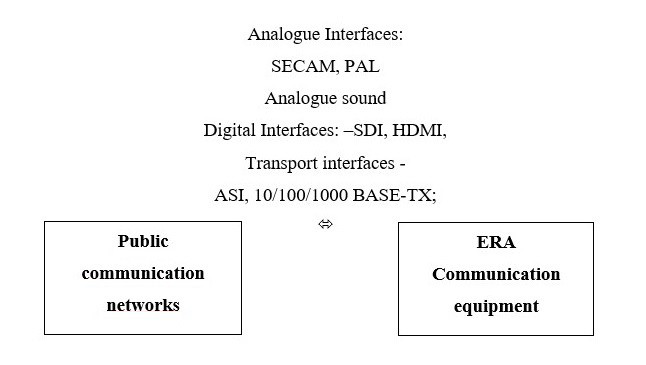
Figure 1.
6. Operating conditions
6.1. Climatic service conditions
The equipment operates at ambient temperature from +5 0C to +40 0C.
6.2. Mechanical service conditions
The equipment must not have mechanical resonance and must comply with all requirements after exposure to sinusoidal vibration in the OFF state for 90 min. with an acceleration amplitude of 4g in the frequency range of 5-80 Hz.
6.3. Power Supply of the Equipment
The parameters of the equipment comply with the requirements given in this document when the power supply voltage changes:
- from 20.4 V to minus 72 V (with DC power supply);
- from 187 V to 242 V (with AC power supply rated voltage 220 V and frequency 50 Hz).