Stationary Radio Relay Systems
 LLC “Typhoon Svyaz Montazh” (group of companies “Typhoon Svyaz”) offers modern radio relay systems (RRS) "ERA-M" to potential consumers. Our equipment is universal, it is designed for digital transmission of any information and it allows a consumer to work with any formats of input and output signals.
Technical specification for digital radio relay systems “ERA M-4”; “ERA M-6N”; “ERA M -6V”; “ERA M -7”; “ERA M -7RV”; “ERA M-8”; “ERA M -8RN”; “ERA M -8RV”; “ERA M -10”; “ERA M -11”; “ERA M -13”.
Name, purpose, completeness of communication means and the functions performed by them.
Digital radio relay stations (DRRS) “ERA M -4”; “ERA M-6N”; “ERA M-6V”; “ERA M -7”; “ERA M -8”; “ERA M -11”; “ERA M -13” operate in frequency bands:
- 3.6–4.2 GHz (ERA M -4);
- 5.925–6.425 GHz (ERA M -6Н);
- 6.425–7.11 GHz (ERA M -6В);
- 7.25–7.55 GHz (ERA M -7);
- 7.55–7.75 GHz (ERA M -7РВ);
- 7.9–8.4 GHz (ERA M -8);
- 8.4–8.5 GHz (ERA M -8РН);
- 8.5–8.7 GHz (ERA M -8РВ);
- 10.38–10.68 GHz (ERA M -10);
- 10.7–11.7 GHz (ERA M -11);
- 12.75–13.25 GHz (ERA M М-13).
Digital radio relay stations (DRRS) are designed to transmit digital streams, digital television signals with speeds of 34 Mbit / s with modulation of QPSK; n31. 66 Mbit / s (n= 1.5) by COFDM with modulation of 64 QAM, and are also designed to transmit Ethernet signals at speeds of 310 Mbit / s and 620 Mbit / s ("co-channel" mode).
DRRS have the following interfaces with the public communication network:
- E3; 10/100/1000BASE-T(X);
- ASI;
- optical interfaces with a transmit / receive frequency of 1,310/1,550 nm.
DRRS includes the modules:
1) Receiving and transmitting equipment (RTE) with intermediate frequency (IF) 70 and 950-2,150 MHz
- RTE ERA М-4 (3.6–4.2 GHz);
- RTE ERA М-6N (5.925–6.425 GHz);
- RTE ERA М-6N (5.925–6.425 GHz);
- RTE ERA М-6V (6.425–7.11 GHz);
- RTE ERA М-7 (7.25–7.55 GHz);
- RTE ERA М-7RV (7.55–7.75 GHz);
- RTE ERA М-8 (7.9–8.4 GHz);
- RTE ERA М-8RN (8.4–8.5 GHz);
 RTE ERA М-8RV (8.5–8.7 GHz);
- RTE ERA М-10 (10.38–10.68 GHz);
- RTE ERA М-11 (10.7–11.7 GHz);
- RTE ERA М-13 (12.75–13.25 GHz);
2) Modem equipment " MD-155»
- 155 Mbit/s-64 QAM-28 MHz, 1000 Base-TX;
3) Modem equipment " MD-310»
- 310 Mbit/s -64 QAM-56 MHz, 1000 Base-TX;
4) Modem equipment " MD-620»
- 620 Mbit/s-64 QAM-56 MHz, "co-channel" mode; 1000 Base-TX;
5) Optical Converter " ASI-OPTIC Converter»
- transmit /receive frequency 1,310/1,550 nm;
6) Modulator " MD ASI»
- 34 Mbit/s -QPSK-28 MHz, ASI input;
7) Demodulator " DM ASI»
- ASI output;
8) Interface Converter " ASI-E3»
- ASI - " E3 " conversion;
9) Modulator " MD COFDM»
- QAM 64 with COFDM; input interfaces: ASI, 10 / 100 Base-TX;
10) Demodulator " DM COFDM»
- output interfaces: ASI, 10/100 Base TX;
11) Transmitter Control Unit
- «Injector Pout»;
12) Service Communication Unit " ACD-111»
- It converts four analog balanced audio signals into a digital stream and back.
1. Parameters of receiving and transmitting equipment
1.1. The plan of the equipment radio channels frequencies distribution
 1.1.1. Receiving and transmitting equipment operates in frequency bands:
- 3.6–4.2 GHz;
- 5.925–6.425 GHz;
- 6.425–7.11 GHz;
- 7.25–of 7.55 GHz;
- 7.55–7.75 GHz;
- 7.9-8.4 GHz;
- 8.4–8.5 GHz;
- 8.5-8.7 GHz;
- 10.38–10.68 GHz;
- 10.7–11.7 GHz;
- 2.75–13.25 GHz1.
1.1.2. The frequency spacing between the adjacent broadband radio channels is, MHz:
- 7/14/28/56 (for frequency bands 6, 7; 8; 10; 13 GHz);
- 30 (for 4GHz band);
- 10/20/40 (for frequency bands 4; 6, 10; 11 GHz),
Depending on the signal rate and modulation method, (see Table 1.)
| Total transmission rate, Mbit/s |
Method of modulation |
Frequency spacing between adjacent broadband radio channels, MHz |
| 34 | QPSK | 28 / 30 / 40 |
| n x 31.66, where: | COFDM | |
| n = 1 | 64 QAM | 7 / 10 |
| n = 2 | 64 QAM | 14 / 20 |
| n = 3 | 64 QAM | 28 / 30 / 40 |
| n = 4 and 5 | 64 QAM | 56 / 40 |
| 155 | 64 QAM | 28 / 30 / 40 |
| 320 | 64 QAM | 56 |
| 640 | 64 QAM | 56 (in "co-channel" mode») |
Table 1
1.2. Signal power at the output of the microwave path of the transmitter
1.2.1. The deviation of the level of the effective power value from the nominal value is within, dB… 2
1.2.2. The maximum level of the effective value of the transmitter signal power is not more than, W…20 W.
1.3. Characteristics of equipment radio emission
1.3.1. The spectra of the emitted signals of equipment with QPSK with a digital signal transmission rate of 34.368 Mbit/s correspond to the template shown in Figure 1.

Figure 1.
1.3.2. Спектры излучаемых сигналов оборудования с модуляцией 64 QAM соответствуют маске, приведенной на Рисунке 2.
1.3.2. The spectra of the emitted signals of the equipment with modulation 64 QAM correspond to the template shown in Figure 2.
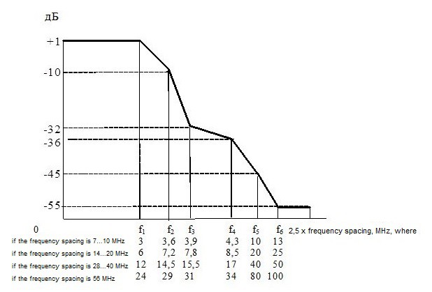
Figure 2.
1.4. Spectral components of out-of-band radiation at the point C', are not more than, dBm …37
1.5. The levels of side radiation at the point C ' are not more than, dBm in the frequency band:
- 30 MHz ...21.2 GHz-50
- 21.2 GHz ... 26 GHz -30
1.6. The level of the microwave signal at the digital equipment receiver input (see Table 2).
| Modulation | Frequency spacing between adjacent broadband radio channels, MHz | Operating frequency range, GHz | Minimum signal level at receiver input, dBm, max, BER= |
||
| 10-3 | 10-6 | 10-8 | |||
| QPSK | 28 / 40 | 4 ÷ 7 | - 79 | - 76 | - |
| 8 ÷ 13 | - 87 | - 75 | - | ||
| 64 QAM | 7 / 10 | 4 ÷ 7 (with COFDM) | - 76 | - 76 | - 76 |
| 8 (with COFDM) | - 75 | - 75 | - 75 | ||
| 14 / 20 | 4 ÷ 7 (with COFDM) | - 73 | - 73 | - 73 | |
| 8 (with COFDM) | - 72 | - 72 | - 72 | ||
| 28 / 30 | 4 ÷ 7 (with COFDM) | - 70 | - 70 | - 70 | |
| 4 ÷ 7 | - 69,5 | - 67,5 | - 64,5 | ||
| 8 ÷ 11 | - 68,5 | - 65,5 | - 63,5 | ||
| 13 | - 67 | - 64 | - 62 | ||
Table 2.
2. Modem equipment interface parameters
2.1. E3 modem digital equipment interface parameters
2.1.1. Digital signal rate at input/output at TT ' points, Mbit/s:
- 34.368 ±20x10-6
2.1.2. Interface code:
- HDB-3
2.1.3. Parameters of interface at points TT - REC. ITU-T
- G. 703
2.1.4. Phase jitter and phase drift - REC. ITU-T
- at input - G. 823
- at output-G. 751
- step-function response - G. 751
2.2. The parameters of the electrical interface of the Ethernet 10/100/1000 BASE-T (X) signals are given in table 3.
| Parameter | 10BASE-T | 100BASE-TX | 1000BASE-T |
| Transmission medium | Unshielded symmetric pair of category 3 | 2 symmetric pairs (STP or UTP) of category 5 4 |
Symmetric pairs of Category 5 |
| Topology | Star | Star | Point-point |
| Code | Manchester | MLT3, 4V/5V | 4D-PAM5 |
| Linear data transfer rate, Mbit/s | 10 | 125 | 1,000 |
| Maximum segment length, m | 100 | 100 | 100 |
Table 3.
2.3. Parameters of the optical interface
2.3.1. The wavelength of the optical signal ranges from 850 to 1,550 nm.
2.3.2. The error rate is not more than 10-10 when the signal attenuation in the optical cable is not less than 30 dB.
2.4. Parameters of the ASI-asynchronous serial interface are given in Table 4
| № | Parameters | Value |
| 1 | Digital stream rate, Mbit / s | 270±27*10-3 |
| 2 | Signal swing, mV | 800 ± 80 |
| 3 | Maximum rise or fall time measured at levels 0.2 and 0.8 ns | 1,2 |
| 4 | The allowable value of the time jitter as a percentage of the duration of the clock interval | 10 |
| 5 | The allowed value of the aligned jitter as a percentage of the duration of the clock interval | 8 |
| 6 | Attenuation of misalignment in the frequency band from 5 MHz to 270 MHz for R = 75 Ohms, dB, not less than | 15 |
Table 4.
3. Conditions of use in the public communication network
DRRS are used for operation of the communication networks in Russia in accordance with:
- Order of the Ministry of Information Technologies and Communication of the Russian Federation No. 25 of 27.02.2007 "About approval of regulations on the use of radio relay communication systems. Part I. Regulations on the use of digital radio relay communication systems of plesiochronous digital hierarchy»;
- Order of the Ministry of Information Technologies and Communication of the Russian Federation No. 57 of 20.02.2012 "Alterations to regulations on the use of radio relay communication systems. Part I. Regulations on the use of digital radio relay systems of communication of the plesiochronous digital hierarchy approved by the Order of the Ministry of Information Technologies and Communication of the Russian Federation No. 25 of 27.02.2007 " regarding frequency bands: 7.55-7.75 GHz; 8.4-8.5 GHz; 8.5-8.7 GHz;
- Order of the Ministry of Information Technologies and Communication of the Russian Federation No. 26 of 27.02.2007 "About approval of regulations on the use of radio relay communication systems. Part I. Regulations on the use of digital radio relay communication systems of synchronous digital hierarchy»;
- Order of the Ministry of Information Technologies and Communication of the Russian Federation No. 7 of 24.01.2008 "About approval of regulations on the use of the equipment of systems of television broadcasting. Part II. Regulations on the use of the equipment of networks of cable television broadcasting " regarding requirements of Appendix 13 (optical converters); Appendices 10 of item 1.5 (modulators / demodulators COFDM);
- Order of the Ministry of Information Technologies and Communication of the Russian Federation No. 39 of March 30, 2007 "About approval of regulations on the use of digital systems of transmission of television and sound broadcasting" regarding requirements of Appendix 6 (ASI interface).
4. Diagrams for connection to the public communication network (shown in Figure 3).

Figure 3
 5. Operating conditions
5.1. Climatic conditions of operation
DRRS has a climatic version 1B and is installed separately: the equipment installed indoors operates at an ambient temperature of +5 0C to + 40 0C, and the equipment installed outdoors operates at an ambient temperature of minus 50 0C to +50 0C
5.2. Mechanical operating conditions
The equipment must not have mechanical resonance and must comply with all requirements after exposure to sinusoidal vibration in the OFF state for 90 minutes:
- with an acceleration amplitude of 2 g in the frequency range 10-70 Hz for indoor equipment;
- with an acceleration amplitude of 4 g in the frequency range 1-80 Hz for equipment installed outdoors.
5.3. Equipment power supply
The parameters of the equipment comply with the requirements given in this document when the supply voltage changes:
- from 20.4 V to minus 72 V (with DC power supply);
- from 187 V to 242 V (with AC power supply rated voltage 220 V and frequency 50 Hz).